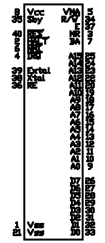
| PIN | Signal | Direction | Description |
| 9-20, 22-25 | Address | Output | Address bus - drive 1 TTL load and 90 pF |
| 26 - 33 | Data | Biderectional | Data bus - drive 1 TTL load and 130 pF. |
| 2 | HALT | Input | When HALT is low, the machine stops at the end of an instruction, BA goes high, VMA goes low. |
| 34 | R/W | Output | 1 = Read/0 = Write. Drives one standard TTL load and 90 pF. |
| 5 | VMA | Output | 1 = indicates there is a valid address on the address bus. Drives one standard TTL load and 90 pF. |
| 7 | BA | Output | 1 = indicates the machine has stopped and the address bus is available. Result of HALT input being low, or the machine executing a WAIT instruction. |
| 40 | RESET | Input | Low = machine is inactive. Low to High transition starts the reset process. |
| 4 | IRQ | Input | Low indicates a request to execute the interrupt sequence. |
| 6 | NMI | Input | Low indicates a request to execute the non-maskable interrupt sequence. |
| 3 | MR | Input | Low causes internal clock to be stretched to accommodate slow memory. |
| 36 | RE | Input | 1 = internal RAM is enabled. 0 = internal RAM is disabled. |
| 38,39 | EXTAL, XTAL | n/a | Used for external crystal or clock input. |
| 37 | E | Output | Enable - phase 2 of internal clock. Drives 1 TTL load and 130 pF. |
| 35 | SBY | Power | Provides Vcc for the first 32 bytes of internal RAM and the RAM Enable (RE) logic. |